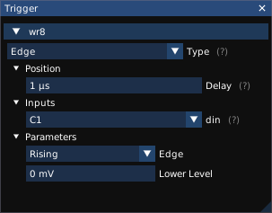
The Setup / Trigger menu opens the trigger properties dialog (Fig. 25.1).
The Type dropdown allows the type of trigger to be chosen. The list of available triggers depends on the instrument model and installed software options.
The Position field specifies the time from the start of the waveform to the trigger point. Positive values move the trigger later into the waveform, negative values introduce a delay between the trigger and the start of the waveform. 1
The remaining settings in the trigger properties dialog depend on the specific trigger type chosen.
All serial pattern triggers take one or two pattern fields, a radix, and a condition.
For conditions like “between" or “not between" both patterns are used, and no wildcards are allowed. For other conditions, only the first pattern is used.
Patterns may be specified as ASCII text, hex, or binary. “Don’t care" nibbles/bits may be specified in hex/binary patterns as “X", for example “3fx8" or “1100010xxx1".
Triggers when a signal stops toggling for a specified amount of time.
| Signal name | Type | Description |
| din | Analog or digital | Input signal |
| Parameter name | Type | Description |
| Edge | Enum | Specifies the polarity of edge to look for (rising or falling) |
| Dropout Time | Int | Dropout time needed to trigger |
| Level | Float | Voltage threshold |
| Reset Mode | Enum | Specifies whether to reset the timer on the opposite edge |
Triggers on edges in the signal.
Edge types “rising" and “falling" are self-explanatory. “Any" triggers on either rising or falling edges. “Alternating" is a unique trigger mode only found on certain Agilent/Keysight oscilloscopes, which alternates each waveform between rising and falling edge triggers.
| Signal name | Type | Description |
| din | Analog or digital | Input signal |
| Parameter name | Type | Description |
| Edge | Enum | Specifies the polarity of edge to look for |
| Level | Float | Voltage threshold |
TODO: This is supported on at least LeCroy hardware, but it’s not clear how it differs from pulse width.
Triggers when a high or low pulse meeting specified width criteria is seen.
| Signal name | Type | Description |
| din | Analog or digital | Input signal |
| Parameter name | Type | Description |
| Condition | Enum | Match condition (greater, less, between, or not between) |
| Edge | Enum | Specifies the polarity of edge to look for |
| Level | Float | Voltage threshold |
| Lower Bound | Int | Lower width threshold |
| Upper Bound | Int | Upper width threshold |
Triggers when a pulse of specified width crosses one threshold, but not a second.
| Signal name | Type | Description |
| din | Analog | Input signal |
| Parameter name | Type | Description |
| Condition | Enum | Match condition (greater, less, between, or not between) |
| Edge Slope | Enum | Specifies the polarity of edge to look for |
| Lower Interval | Int | Lower width threshold |
| Lower Level | Float | Lower voltage threshold |
| Upper Interval | Int | Upper width threshold |
| Upper Level | Float | Upper voltage threshold |
Triggers when an edge is faster or slower than a specified rate.
| Signal name | Type | Description |
| din | Analog | Input signal |
| Parameter name | Type | Description |
| Condition | Enum | Match condition (greater, less, between, or not between) |
| Edge Slope | Enum | Specifies the polarity of edge to look for |
| Lower Interval | Int | Lower width threshold |
| Lower Level | Float | Lower voltage threshold |
| Upper Interval | Int | Upper width threshold |
| Upper Level | Float | Upper voltage threshold |
Triggers when a byte or byte sequence is seen on a UART.
| Signal name | Type | Description |
| din | Analog or digital | Input signal |
| Parameter name | Type | Description |
| Bit Rate | Int | Baud rate |
| Condition | Enum | Match condition |
| Level | Float | Voltage threshold |
| Parity Mode | Enum | Odd, even, or no parity |
| Pattern | String | First match pattern |
| Pattern 2 | String | Second match pattern |
| Polarity | Enum | Idle high (normal UART) or idle low (RS232) |
| Radix | Enum | Radix for the patterns |
| Stop Bits | Float | Number of stop bits |
| Trigger Type | Enum | Match data pattern or parity error |
Triggers when a signal goes above or below specified thresholds.
The available configuration settings for this trigger vary from instrument to instrument.
| Signal name | Type | Description |
| din | Analog | Input signal |
| Parameter name | Type | Description |
| Condition | Enum | Specifies whether to trigger on entry or exit from the window, and whether to trigger immediately or after a time limit. |
| Edge | Enum | Specifies which edge of the window to trigger on |
| Lower Level | Float | Lower voltage threshold |
| Upper Level | Float | Upper voltage threshold |
1This is a different convention than most oscilloscopes, which typically measure the trigger position from the midpoint of the waveform. Since ngscopeclient decouples the acquisition length from the UI zoom setting, measuring from the midpoint makes little sense as there are no obvious visual cues to the midpoint’s location.